
Before you build, plan your lift space.
Choose your car dimensions and compare side and rear counterweight layouts.
Open the interactive planner (Arabic) →Purpose and scope
This guide provides a planning reference for site engineers, consultants and contractors preparing a lift shaft before manufacturing and installation. It brings together the civil and mechanical requirements used by Betis for residential, commercial and existing-building projects in Basra and across Iraq.
This guide states Betis planning and preparation requirements. The approved shop drawing, lift calculations, component data and mandatory project safety requirements remain the basis for manufacturing and installation.
Essential technical terms
- Shaft / Hoistway
- The vertical structural space in which the car and counterweight travel.
- Pit
- The vertical distance from the finished floor at the lowest landing to the pit floor.
- Overhead
- The distance from the finished floor at the highest landing to the underside of the shaft roof, accounting for any lower beams or obstructions.
- Counterweight
- A mass that balances the car and a proportion of rated load to reduce traction demand. Half the rated load is used in some Betis designs; the balance ratio and actual counterweight mass are established by calculation.
- Static load on the machine
- The loads acting on the machine and shaft depend on suspension, rope routing and support reactions. Car, counterweight, ropes and rated load contribute; a single addition formula does not cover every 1:1 and 2:1 arrangement.
- MR — Machine Room
- A lift whose machine and controller are installed in a dedicated room separate from the shaft, in accordance with the approved shop drawing.
- MRL — Machine-Room-Less
- A lift whose machine is installed inside the shaft, without a separate rooftop machine room.
Counterweight position and car dimension formulae
Betis uses the following formulae for the initial planning of single-entrance lifts. Measure the internal clear shaft dimensions after allowing for finishes and checking the narrowest point over the full shaft height. All formula values are in centimetres.
1. Rear counterweight
Planning allowance for rails, frame and clearances on both sides.
Planning allowance for the rear counterweight and the front door assemblies and sills.
2. Side counterweight
Allows for the side counterweight, rails, frame and clearances.
Planning allowance for the door assembly, sills and related clearances. Betis selects the deduction within the range to suit the equipment.
When can car depth increase?
- Open frontage: approximately 10–12 cm may be recovered with an approved landing-door and sill position.
- Manual / semi-automatic landing door: mounting its frame on the outside shaft face may recover approximately 10 cm. Selecting a manual door alone does not guarantee extra depth.
The shop drawing establishes the actual gain. Do not automatically add both gains together or add a gain already included in the door position.
These are initial planning formulae. Manufacturing dimensions require review of the equipment, clearances and permitted area for the rated load, followed by shop-drawing approval.
Open-front shaft arrangement
Some projects leave the shaft front open during civil works, then install the approved door frontage and enclosure instead of building a wall with a separate opening at each landing.
Potential space recovery
Positioning the landing door and sill at the slab edge may recover part of the front-wall thickness. Betis estimates an additional 10–12 cm of car depth in some arrangements. The actual gain must be established in the drawing; it is not guaranteed for every shaft.
When is this arrangement considered?
- Narrow shafts: to make effective use of existing-building space.
- Centre-opening doors: to coordinate panel retraction and frame fixing.
- Steel and panoramic structures: to coordinate fixings with the architectural frontage.
- Vertical alignment: to align landing doors and reduce opening errors between floors.
Closing the frontage and completing finishes
Where an open-front shaft is approved, Betis first installs and fixes the landing doors in their approved positions. After door installation, the contractor or building owner must close the remaining openings beside and above the doors under Betis supervision, using masonry or an engineered steel framework with suitable enclosure and cladding, as detailed in the approved drawings.
Final finishes may use marble, ceramic or other decorative materials appropriate to the building and architectural design. Clear door-opening dimensions must be maintained, without obstructing door movement or access to approved maintenance points.
Lift systems and structural requirements
Installation systems
- MR: a geared or gearless machine, according to the design. Provide separate cooling and appropriate ventilation as specified in the thermal requirements below.
- MRL: Betis uses gearless machines installed inside the shaft, with safe maintenance and rescue access.
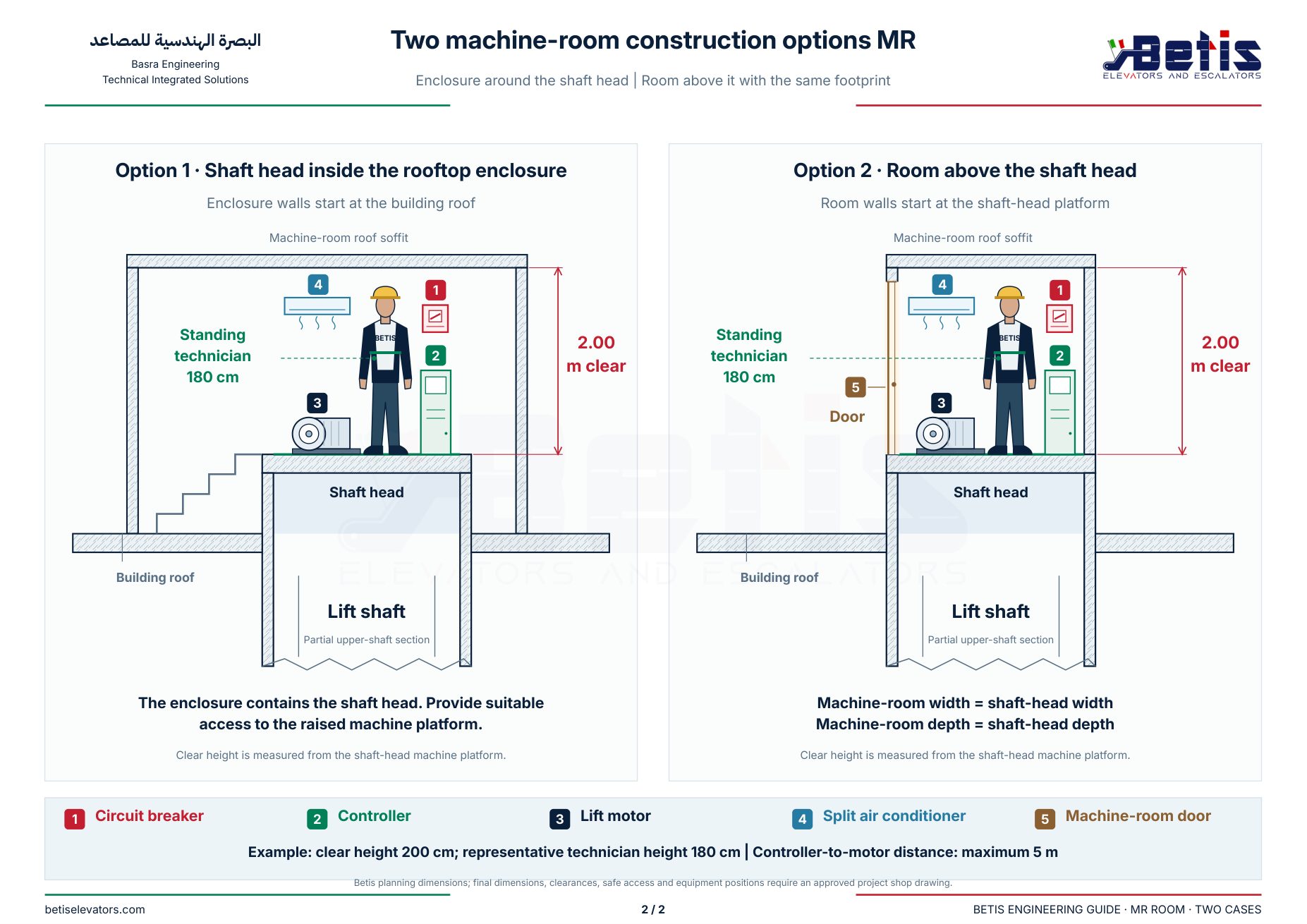
Two machine-room construction options
- Rooftop enclosure around the shaft head: the enclosure walls start at the roof of the top floor and surround the projecting shaft head. Provide suitable access to the raised machine platform.
- Room above the shaft head: room walls start at the top of the shaft enclosure and match its width and depth, with a room door and safe access as approved in the drawing.
Shaft construction
- Reinforced concrete: brackets may be fixed after the concrete, anchors and load capacity have been verified.
- Masonry with concrete ties: Betis proposes horizontal ties on the right, left and rear sides at vertical intervals of 150–160 cm. A structural engineer must check sections, reinforcement and positions against rail loads and approved bracket spacing.
- Steel structure: considered for existing buildings, external and panoramic lifts; designed for the lift-specific loads and reactions.
Controller, electrical supply and cooling
MRL controller location
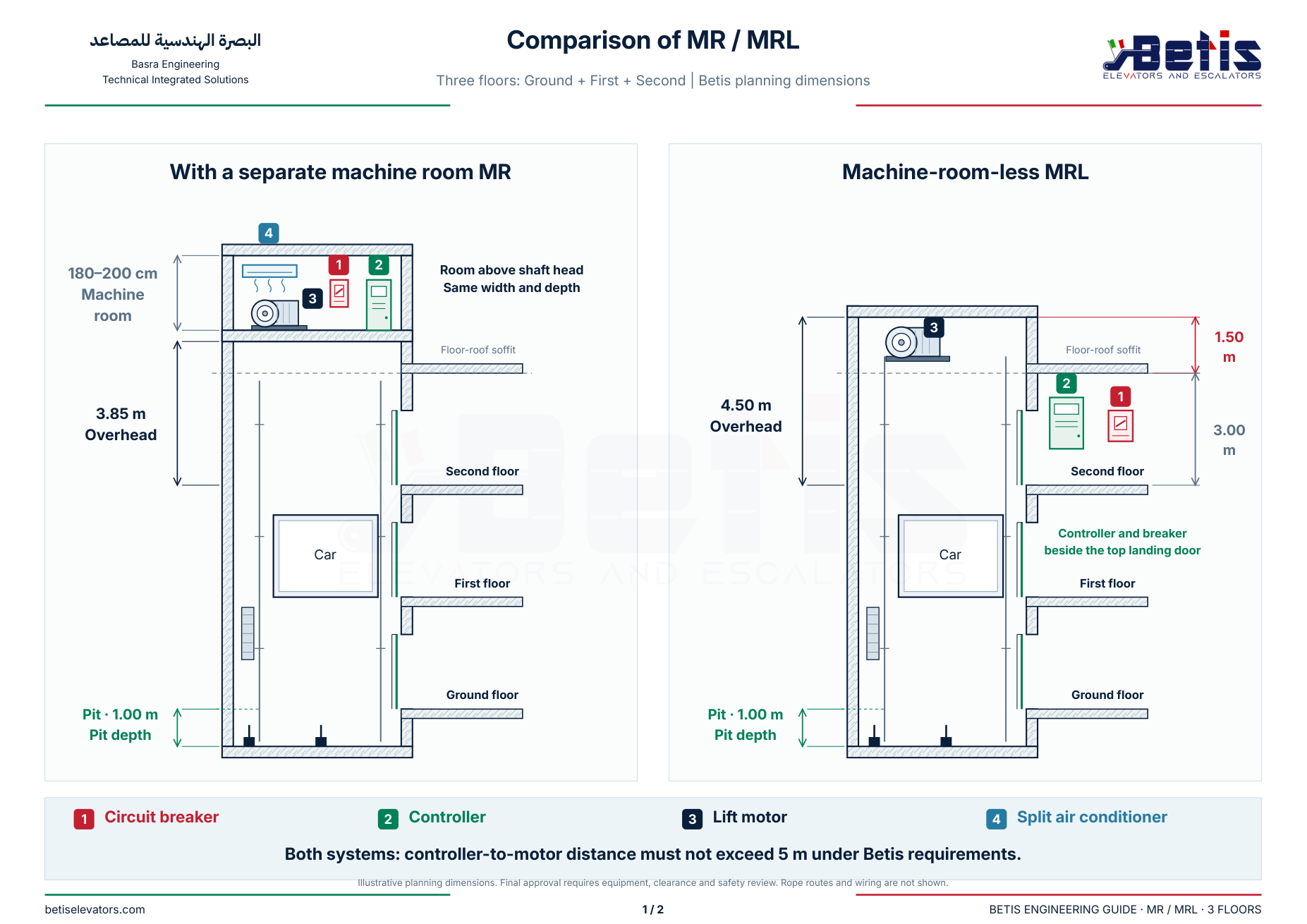
Install the controller beside the lift door at the highest landing, with no more than 5 m between controller and motor, as required by Betis. Approve the location and cable route in the shop drawing and provide safe maintenance and rescue access. The same 5 m maximum also applies to the MR arrangement.
Power supply and circuit breaker
The contractor or building owner must bring the supply cable to the controller in the machine room, or to the top-floor controller cabinet for MRL, and provide a suitable circuit breaker. Betis specifies the cable, conductor sizes and breaker rating according to lift load, motor power, equipment data and supply-route length. Motor connections from the controller follow the approved electrical drawing.
Required supply: three phases, neutral and protective earth.
L1 + L2 + L3 + N + PE (Earth)
Machine-room cooling
A machine room requires a separate split air-conditioning unit of at least 1.5 refrigeration tons under Betis requirements. Increase capacity where necessary for room area, equipment heat load, insulation and site conditions. For MRL, coordinate shaft and controller-cabinet ventilation and cooling to maintain required operating conditions.
Two machine-room construction options — 180 cm technician
Drawings use Betis planning dimensions. Construction details, clearances and equipment positions require project-specific approval.
View full-size drawing ↗
Lift pit and groundwater
Betis determines pit depth according to rated load, speed, components and site conditions. Projects in Basra and Iraq require attention to waterproofing, under-car clearance, safety spaces and buffer capacity.
Scroll horizontally to see all columns
| Pit depth | Category | Study and approval conditions |
|---|---|---|
| 150 cm or more | Planning reference | Consider for higher loads, speeds and travel. Final depth depends on buffers, safety spaces and the approved shop drawing. |
| 100 cm | Betis planning option | Consider within the proposed company range: up to 7 floors, 1 m/s and 1000 kg. Verify clearances, refuge spaces and buffer capacity before approval. |
| 50–75 cm | Reduced-pit solution | A special solution for existing buildings, requiring an approved protection system and coordinated buffers and clearances. More overhead does not automatically compensate for a shallow pit. |
| 12 cm | Dedicated home lifts | Applies to the specified Betis model and its system certification, with proposed 3000 mm overhead. It does not apply to conventional lifts generally. |
Planning rule: above 7 floors, 1 m/s or 1000 kg, reassess the pit and consider 150 cm or more according to the selected system. Do not approve final depth before verifying buffers and safety spaces.
The search phrase “home lifts without a pit” does not mean every system has zero pit depth. The option in this guide requires 12 cm for the approved model.
Overhead, car height and door height
Measure overhead from the finished floor at the highest landing to the underside of the shaft roof, identifying obstructions. Check the machine, suspension, car roof, refuge spaces and clearances at the final positions of travel.
Scroll horizontally to see all columns
| System | Overhead | Internal car height | Door height |
|---|---|---|---|
| MR / geared | 385 or more | 220–230 | 210 |
| MR / existing building | 325–350 | Up to 210 | 200 |
| MRL | 450 | 220–240 | 210–220 |
| MRL / special arrangement | 400 | 210 | 200 |
MR and MRL comparison — three floors
Drawings use Betis planning dimensions. Construction details, clearances and equipment positions require project-specific approval.
View full-size drawing ↗
Doors and opening directions by shaft width
Automatic doors
Select telescopic side-opening or centre-opening doors according to clear shaft width, door frame, operator and panel retraction space. These are Betis planning options; match them to the door manufacturer’s drawings and verify shaft plumbness and required clearances.
Scroll horizontally to see all columns
| Shaft width | Proposed load (kg) | Side opening | Centre opening | Door height |
|---|---|---|---|---|
| 1300–1499 | 320 | 700; 1300 shaft width requires a specific check | Not standard in this schedule | 2000 |
| 1500 | By car design | 800 | Not listed as standard | 2000 |
| 1600 | 480–630 | 800 | 700 | 2000 |
| 1800–1900 | 630–800 | 900 | 800 | 2000 |
| 2000 or more | 1000 | 1000 | 900 | 2100 |
| 2200 or more | 1250 | 1100 | 1000 | 2100 |
Rated load cannot be inferred from shaft width alone; assess car area, mass and lift arrangement. Door accessibility requirements need a separate check.
Semi-automatic / manual landing doors
- Consider for residential buildings and narrow shafts, with proposed opening widths of 700, 800, 900 or 1000 mm according to the shaft and car.
- A conventional arrangement may occupy around 12 cm of depth, depending on the model.
- Mounting the frame on the external frontage may recover around 10 cm in some cases, subject to sill, enclosure, clearance and protection coordination.
- A manual landing door does not eliminate any car door required by the approved system.
Installation note: consider centre-opening doors for commercial and service buildings and side-opening doors where frontage is limited. Opening and closing time depends on the model and settings, not solely on opening direction.
Suspension, rated loads and car areas
The Engineers’ Guide
1:1 suspension
The car travels at rope speed. Betis uses this arrangement in some geared solutions from 320 to 800 kg.
The Engineers’ Guide
2:1 suspension
The car travels at half rope speed. Used in Betis higher-load and gearless solutions according to system design. Suspension ratios are not universally determined by load alone.
Betis adopts the maximum areas in the dimensional schedule. Final verification includes the full available car area and any entrance recesses included in the measurement, together with car mass and lifting-system capacity.
Scroll horizontally to see all columns
| Loadkg | Persons* | Max. aream² | Clear car | Planning shaft** | Clear door opening | |||
|---|---|---|---|---|---|---|---|---|
| Width | Depth | Width | Depth | Width | Height | |||
| 320 | 4 | 0.90 | 900 | 1000 | 1400 | 1500 | 700 | 2000 |
| 480 | 6 | 1.30 | 1100 | 1150 | 1600 | 1650 | 800 | 2000 |
| 630 | 8 | 1.66 | 1100 | 1400 | 1600 | 1900 | 800 | 2000 |
| 800 | 10 | 2.00 | 1350 | 1400 | 1900 | 1900 | 800–900 | 2000 |
| 1000 | 13 | 2.40 | 1400 | 1600 | 2000 | 2200 | 900–1000 | 2100 |
| 1250 | 16 | 2.90 | 1600 | 1800 | 2200 | 2400 | 1000–1100 | 2100 |
| 1600 | 20 | 3.56 | 1400 | 2500 | By approved shop drawing | 1100 | 2100 | |
| 2000 | 25 | 4.20 | 1500 | 2700 | By approved shop drawing | 1200 | 2200 | |
1600 kg car: 1400 mm width × 2500 mm depth; geometric area 3.50 m². Verify the actual available area using the approved measurement method.
* Betis uses a planning weight of 75–80 kg per person. The listed loads and passenger counts fall within that range, including 630 kg for 8 persons and 1000 kg for 13 persons. Rated load in kilograms remains the binding limit and must not be exceeded even with fewer occupants.
** Shaft sizes are planning examples for different arrangements. They do not all derive from the Section 03 deductions and do not guarantee that a particular door will fit. The 1600 kg row requires the shaft to be redesigned for the 2500 mm-deep car. The 2000 kg car is 1500 mm wide × 2700 mm deep, with a geometric area of 4.05 m²; include all available area and tolerances before manufacture.
Scroll horizontally to see all columns
| Load (kg) | Suggested application |
|---|---|
| 320 | Small residential / villa |
| 480 | Medium residential |
| 630 | Residential / accessibility study |
| 800 | Residential and commercial |
| 1000 | Commercial buildings and offices |
| 1250 | Intensive use / hotels |
| 1600 | Bed / service lift, subject to requirements |
| 2000 | Goods / specific study |
Common shaft-preparation mistakes and how to avoid them
Early review of the following points helps reduce rework and installation conflicts. Read the corrective actions with the approved project drawing and requirements.
01 · Dimensions, plumbness and frontage
01 Relying on measurements from one floor
A single-floor measurement can conceal shaft misalignment or narrower sections at other levels.
Correct action: Measure every floor, check shaft plumbness and identify the narrowest finished dimensions over the full lift travel before approving the car size.
02 Building door openings without an approved drawing
Inconsistent opening sizes, levels or vertical alignment may prevent door installation and require civil alterations. Closing the frontage too early may also lose usable depth.
Correct action: Follow the Betis drawing. Where open frontage is approved, leave it open until doors are installed, then close it under Betis supervision. Depending on the project, this can recover approximately 10–12 cm of planning depth.
03 Ignoring the door-panel return space
A centre-opening or telescopic door may not fit if the shaft is too narrow for the requested opening.
Correct action: Approve the door type and clear opening only after checking frame, operator, panel-return space and clearances.
02 · Pit and overhead
04 Omitting complete pit waterproofing
Water and moisture, particularly in high-groundwater areas such as Basra, can damage buffers and electrical components and affect operation.
Correct action: Provide complete waterproofing and verify that the pit is dry and free from leakage before installation and operation.
05 Routing services through the lift movement zone
Drainage pipes or pumps in the movement zone obstruct equipment and required clearances.
Correct action: Keep these services outside the lift movement zone. Coordinate any permitted services outside that zone in the approved drawing.
06 Treating overhead as a substitute for pit depth
More overhead does not automatically compensate for a shallower pit; each has separate equipment, clearance and safety requirements.
Correct action: Review pit and overhead independently. Any reduced-pit solution requires suitable equipment and project-specific study and approval.
07 Ignoring beams, hooks and upper obstructions
Measuring only to the roof can overstate the actual available space.
Correct action: Record the lowest levels of relevant beams, hooks and other obstructions, then establish usable clear height against the equipment layout and clearance requirements.
03 · Structure and rail fixing
08 Fixing rails to unengineered masonry alone
Rail brackets fixed to masonry not designed for the loads may provide inadequate support.
Correct action: Provide concrete ties on three sides at Betis planning intervals of 150–160 cm vertically, or an engineered alternative structure. Have sections, reinforcement and anchors structurally checked.
09 Changing dimensions or levels after approval
Changes to openings, finishes or floor levels can invalidate approved measurements.
Correct action: Obtain written approval from Betis Engineering and update the affected drawings and measurements before proceeding.
04 · Power, cooling and car dimensions
10 Incorrect supply or missing protective earthing
A supply or protective device that does not match the selected system, or missing protective earthing, may prevent safe operation.
Correct action: For a three-phase system, provide L1 + L2 + L3 + N + PE, with cable and breaker specified by Betis. Do not change the approved supply without review. Home-lift systems may have different model-specific supply requirements.
11 Omitting machine-room cooling
Temperatures above the manufacturer’s limits can activate thermal protection and stop the lift.
Correct action: Provide a split air conditioner of at least 1.5 refrigeration tons under Betis requirements; verify capacity against room area, heat load and ventilation. Ventilation alone is not an automatic substitute for approved cooling.
12 Failing to weatherproof the machine room
An inadequately protected roof, walls, doors or openings can admit rainwater and dust, potentially damaging the machine, controller and electrical components.
Correct action: Protect the room against water and dust ingress while maintaining ventilation and providing cooling in accordance with approved Betis requirements.
13 Positioning the controller too far from the motor
Exceeding the approved distance may conflict with the specified cable-routing and connection requirements.
Correct action: For MRL, locate the controller beside the highest landing door, no more than 5 m from the motor under Betis requirements. Review cable type and route. The same distance requirement also applies to MR.
14 Increasing car size or finish weight without review
Enlarging the car or using heavy finishes such as marble changes its mass and may exceed the system’s approved area or loads.
Correct action: Recheck car and counterweight masses, machine, ropes, traction, brakes and other components before approval. Maintain the approved rated load and maximum area.
Pre-manufacturing site survey checklist
Manufacturing at the Betis factory must not begin until the following data are documented and the shop drawing is approved:
- Clear shaft measurements: Width and depth at every floor, checking plumbness and the narrowest finished point.
- Pit depth: From the final finished floor at the lowest landing to the pit floor.
- Overhead: From the final finished floor at the highest landing to the roof underside, recording beams and obstructions.
- Floor levels: Number of floors and stops, and vertical distance between successive floors.
- Structural system: Reinforced concrete, masonry with ties, or steel structure, including rail-fixing details.
- Frontage and doors: Opening sizes and locations; approval of open frontage or external frame position where needed.
- Machine and system: Machine-room dimensions and cooling, or MRL arrangement, controller location and distance to the motor.
- Electrical supply: Agree supply cable, circuit breaker and route with Betis; 3 Phase + Neutral + Earth with protective earthing to the approved drawing.
- Waterproofing: Confirm a dry pit and prevention of harmful leakage and moisture.
- Documentation: Clear photographs of the pit, shaft, frontage and roof, with a measured drawing.
Site execution and safety requirements
- Shaft preparation: provide a clean, dry shaft free of debris and timber, with temporary power, lighting and safe access.
- Pit waterproofing: install complete waterproofing and prevent drains and pumps from entering or obstructing the lift movement zone. Coordinate any permitted equipment outside this zone in the drawing.
- Opening protection: Betis requires rigid protective barriers at least 120 cm high during works. The safety supervisor must verify strength, fixing, fall-protection details and site requirements.
- Change control: do not alter door openings, pit depth or floor levels after drawing approval without written approval from the Betis Engineering Department.
Guide approval and project documentation
This guide provides a common planning language for Betis, engineers, consultants and contractors. Project approval is completed through the following documents:
- Final site survey: clear dimensions, finished levels, pit, overhead and door-opening locations.
- Shop drawing: car, counterweight, rails, doors, machine and clearance arrangements, approved by Engineering.
- Lifting-system calculations: masses, loads, traction, balance, anchors, buffers and suitability of every component for the selected system.
- Equipment data: door, machine and controller drawings, plus installation, maintenance and rescue requirements.
- Documented changes: revise dimensions, finishes or rated load only after review and updates to the technical documents.
Keep the reference. Share it with your team.
A print-ready PDF with the technical schedules and explanatory drawings.
Download the guide PDF ↓Share with your team
© Betis Elevators and Escalators — Eng. Ali Hassan Al-Ali
Download directly without a rating or contact details. A cookie helps estimate distinct visitors.
Important planning notes
Plan new buildings; study existing buildings individually.
These dimensions are for initial planning of new buildings, not direct application to existing buildings. Betis provides tailored solutions for existing buildings following a site survey and detailed engineering calculations.
Allow for construction tolerances.
Preferably allow an additional 50–100 mm in clear shaft width and depth beyond the planning dimensions, subject to confirmation by Betis engineers. This allowance is not added automatically and does not replace accurate shaft verticality.
Car width or depth may increase by 50–100 mm after load calculations by Betis engineers. This is a possible outcome, not a requirement or commitment.
Dimensions are approximate and depend on a plumb shaft without inclination. Measure clear dimensions after finishing throughout the shaft height.
For a completely open front without shoulders, with 2300 mm clear opening height, the planner reduces shaft depth by 100 mm while preserving car dimensions. Doors are mounted outside with only 20 mm intrusion, subject to the approved door arrangement.
For loads from 1250 to 2000 kg, Betis prefers a side counterweight. Allow 700 mm beyond car width for the planning arrangement; door requirements may require more width.
Below 1300 mm shaft width, the Betis planning rule proposes semi-automatic doors. At 1500 mm, an 800 mm telescopic door may be proposed, subject to car width and the approved door drawing.
EN 81-20 uses 75 kg per person. Betis uses 75–80 kg per person. For door opening dimensions, contact Betis for a free consultation and drawing.